Selecting piezo products: Everything you need to know
Choosing the right piezo technology can be challenging. We wrote this guide to make sure you can make an accurate comparison between products and manufacters and therefore an informed decision.
Table of contents
Introduction
We know that finding the right piezo product can be a challenge. There are a lot of options available across different manufacturers. And as if that isn’t enough, actuator and stage manufacturers tend to use different terminology in their specs, making it hard to compare two models of a different brand.
As we believe you should be able to choose the product that suits you best, we have created this guide to selecting the perfect piezo actuator or stage for your project. It will explain the different versions and options available, help you to compare the right specs and eventually guide you to the most suitable solution for your project.
Terminology, the terms that really matter
Sensor resolution
The term sensor resolution indicates the smallest motion detectable by the position sensor. This value is the lower limit for the actuator / stage resolution. Sensor resolution is also referred to as sensor sensitivity. It doesn’t tell you anything about the motion specs, but only about the detection of the motion. Big difference.
➜ Don’t be fooled, this is a spec of the sensor, but not of actuator / stage. It’s an easy way to impress customers, but doesn’t tell a lot about the performance of the actuator or stage.
Sensor accuracy
The accuracy of a position sensor represents the absolute deviation with respect to a calibrated, metrologically traceable standard. Sensor accuracy does not necessarily relate to sensor resolution. Sensor inaccuracy is mostly caused by the imperfectness of the sensor scale and by the alignment error of the sensor scale during assembly. The sensor accuracy error is to a great extent repetitive and can be compensated for by means of a lookup table.
➜ This is a tricky one and often misunderstood. You will typically find that these specs are much worse than the precision specs of actuator or stage. But this shouldn’t bother you too much, because the error is very repeatable, once the encoder is installed. Calibration of your system typically takes care of this. In 99% of the cases, this spec isn’t very important.
Actuator / stage resolution (= minimal step size)
Resolution is defined as the smallest, controlled mechanical displacement of a piezo positioning actuator / stage. The resolution is affected by the sensor resolution, mechanical influences (friction, compliance, contact point nonlinearities...) and position control performance. This value is the lower limit for the actuator / stage repeatability. Other terms for stage / actuator resolution are minimal step size or minimal incremental motion (MIM).
➜ Now things are getting interesting. When people talk about precision, this is the one they mean: the smallest step size an actuator or stage can take. In some cases, there can be quite some difference between the actuator / stage resolution and the encoder resolution. Together with actuator / stage repeatability, this is the most important parameter.
Actuator / stage repeatability
Repeatability is defined as the range of positions attained when the actuator / stage is repeatedly commanded to one specific location under identical conditions. There are two types of repeatability.
Unidirectional repeatability: i.e. the ability of an actuator / stage to return to a given point, always coming from the same previously defined point. The value specified is the standard deviation of many moves to the same point.
Bidirectional repeatability: the ability of an actuator / stage to return to a given point coming from a random previous point. The value specified is the standard deviation of many moves from random directions to the same point. The values given on the Xeryon specifications refer to the bidirectional repeatability, unless specified differently.
➜ As said above, a small minimal step size is nice. But you also want to be sure that when moving to a certain position at any moment or from any starting position, you always end up in the exact same position. Open-loop systems struggle with this because the step error is cumulative. However, there can also be huge differences between closed-loop systems, mainly due to the system control.
Things get even worse when moving in two directions, because then the quality of the bearings starts to interfere as well. The longer the distance, the greater the effect. Therefore this is the second most important spec to look at: bi-directional repeatability.
Actuator / stage accuracy
The accuracy of an actuator or stage is directly related to the sensor accuracy. This is a result of the direct-drive principle of an actuator / stage and the small distance between the position sensor and mounting surface.
➜ Don’t focus too much on this one. If you understand encoder accuracy, you also understand actuator / stage accuracy. Some manufacturers confuse actuator / stage accuracy with error motion. This is a separate spec, and a very important one. See below!
Error motion of a rotation stage
According to the ANSI/ASME B89.3.4 standard, the error motion of a rotary stage’s axis of rotation is defined as a change in position relative to the reference coordinate axes, of the surface of a perfect workpiece, as a function of rotation angle, with the workpiece centerline coincident with the axis of rotation. In other words, a rotary stage ideally has one degree of freedom, i.e. the rotation about the z-axis.
However, as perfect rotary stages do not exist, any motion in the remaining five degrees of freedom is referred to as an axis-of-rotation error motion or simply error motion. Depending on the error direction, one can distinguish two radial contributions, one axial and two tilt or wobble contributions. Furthermore, the error motion of a rotary stage can be separated into a synchronous and asynchronous component. The error motion of a stage is often incorrectly referred to as stage runout. A more elaborate explanation of these terms can be found here.
➜ If you’re looking for a rotary stage, make sure to take the error motion into account. A wobbly behaviour of the rotary disk will obviously have a huge impact on your results.
Error motion of a linear stage or actuator
The error motion of a linear actuator / stage is the undesired motion, as a function of the actuator / stage position, in all five degrees of freedom other than the direction of motion. The error motion in the horizontal plane is referred to as straightness error, and the error in the vertical plane as flatness error. The angular error motion components in the different orthogonal directions are called pitch, roll and yaw. Another term for the error motion of a linear actuator / stage is the guiding error or travel error.
A quick word about actuators: Where a stage is designed to approach an error-less motion, even in the case of sideways forces, an actuator is designed to push and to pull. When there is some tolerance on the imperfect motion, an actuator can be used without any additional guiding of the payload. But when you use an actuator and you also need an errorless motion, you will need to add guidings to the payload to keep it on track. So remember: an actuator is for a push / pull motion but a stage can also support the payload in other directions.
➜ Same remark as with the rotary error motion. What’s the point of having great precision when the actuator / stage has unwanted movements? The error motion specs of an actuator / stage are very important, as even small error motions can have a huge effect on your final results. Important for specific projects, but often not the decisive parameter.
Travel speed
The maximum travel speed of the stage or actuator.
➜ Not a difficult one, but often overlooked. If you want to do a lot of measurements, the actuator / stage speed can have a huge impact on your throughput. For scanning measurements (measuring during movement), the speed stability is very important. If you are using long stages or actuators a high travel speed is a must to avoid long waiting times.
Lifetime
Typical lifetimes of stick-slip piezo stages and actuators are about 20 - 30 km. When you do a lot of movements, this threshold is reached within a couple of months. Xeryon ultrasonic piezo products have a life expectancy over > 1000 km. Important to note is that the wearing off of the piezo ceramic generates ceramic dust particles. This is true for all types of piezo systems, but much less prominent in ultrasonic piezo.
These can be harmful for your experiment or equipment.
➜ Lifetime is often forgotten, but you don’t want to buy new equipment too often or end up with ceramic dust in your setup. If you only move the stage or actuator sporadically this parameter is not very important.
Sound and vibrations
Piezo products are vibration based. This is the core principle: The vibrations of the piezo-element are converted into a net motion.
If these vibrations are within the human audible spectrum (20 Hz to 20 kHz) the piezo motor will make a disturbing and audible noise.
A second issue with the vibration frequency of the piezo-element is that it can generate resonance in its environment. Many small components have a resonance frequency in the 1 - 5 kHz spectrum and can start resonating when the piezo stage or actuator is activated. Ultrasonic piezo systems (like the Xeryon products) are vibrating in a spectrum between 80 kHz and 180kHz. They are silent and the risk of bringing resonance in your setup is almost zero.
➜ Noise can be annoying for some applications. If you will be using the piezo motor all of the time, this is something to take into account. Resonance in your experiment can be a bigger issue than noise: be careful for low resonance frequencies!
Holding force and driving force
The driving force explains the force with which the stage or actuator can push or push in the direction of motion. It is important to make a distinction between horizontal and vertical movements. In a horizontal direction in theory any payload can be moved, as long as the friction (and the inertia) allows it. The higher the mass of the payload, the lower the acceleration (F=m*a). Because of the friction in the guidings, the top speed will also drop with heavy payloads.
In the vertical direction it is a different story: a stage or actuator can only lift a payload with a lower vertical force than the driving force of the motor. So, in theory, a 3N stage can lift a 300 gram payload. In reality the lifting force is considerably less than this, because of loss of force during landing on the target position. Horizontally this is not an issue because gravity is perpendicular on the driving axis. This issue typically can be resolved by introducing a mass compensating system, which compensates for the gravity of the payload. This can be done magnetically or mechanically (with springs or counterweights).
The holding force is the force you need to exert on the stage or actuator to move it when it is fixed on a position. A distinction needs to be made between active holding force and passive holding force. Active holding force means that the piezo motor is still active and when the actuator / stage is moved, the motor starts to counter-push. So in this case the holding force equals the driving force. The passive holding force is relevant when the piezo motor isn’t powered on any more. In this case the holding force is generated by the friction between the piezo element and the ceramic driving strip of the stage or actuator. The piezo element is pushed against the strip with a certain force, giving the system a mechanical holding force when the power is off.
➜ Driving force is an important parameter when high accelerations are needed. When speed is not an issue, large masses can be moved with small piezo motors. If you are lifting a payload, much more attention needs to be given to the driving force as gravity comes into play. The passive holding force (when powered off) can be really important when you want to eliminate all kinds of vibrations and distortions out of your setup or when you want to reduce power consumption.
Open-loop vs. closed-loop
In position control, we often speak about open-loop or closed-loop control. In general, open-loop control in motion systems means that there is no position feedback of a moving object. Closed-loop control means that there is some kind of position information that is fed back to the motion controller of a system to help with positioning. A detailed explanation on the open-loop vs closed-loop control can be found here.
More info on all kinds of piezo technology
Many piezo precision products on the market are driven by a stick-slip piezo motor, an ultrasonic piezo motor or a hybrid technology. If you want to know more about the differences, have a look here.
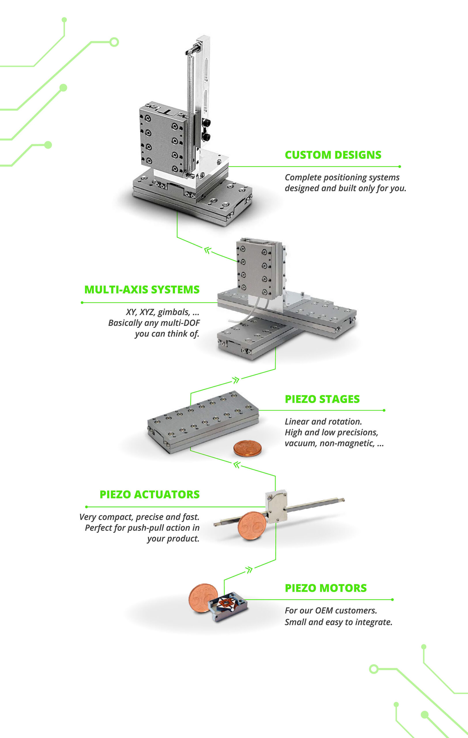
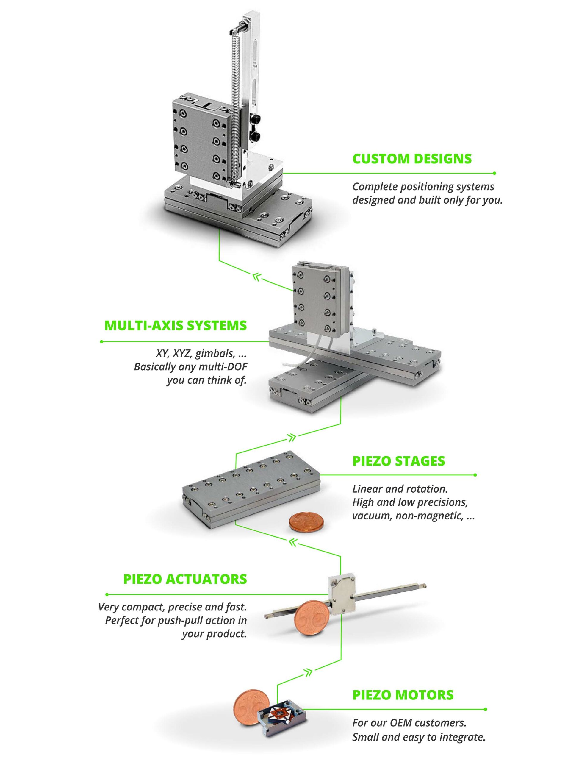
Xeryon: Different levels of implementation
Xeryon claims clients and customers in a wide range of industries, both in OEM and research applications.
From high-performance environments such as medical devices, semicon manufacturing, and space and metrology applications to scientific applications such as materials, imaging and medical research, Xeryon offers (ultrasonic) piezo products for any project imaginable.
From open-loop to closed-loop systems, actuators and stages, non-magnetic and vacuum-compatible products, and vibration-proof components, Xeryon offers it all and can be relied on as your partner in standard or custom precision motion needs.
Trusted by numerous industry leaders